Two Burners, One Heater, Zero Wasted Space
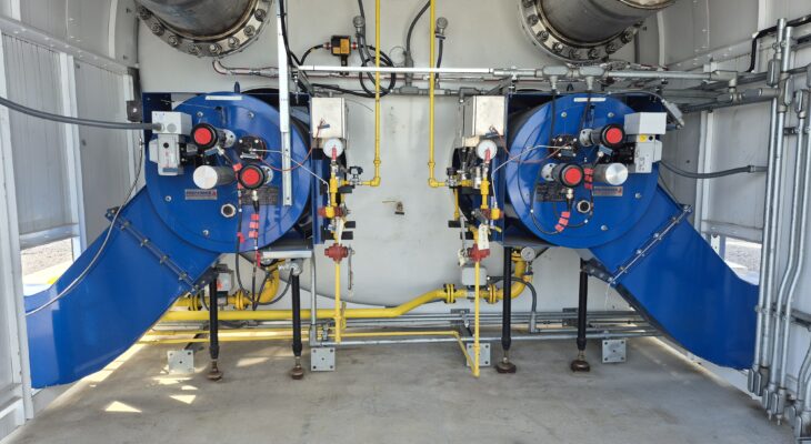
Preferred recently completed a combustion and controls package for a cryogenic facility in Canada. The scope covered burners, burner management and combustion controls, power distribution, and fuel gas piping for a dual-chamber water bath heater, all designed, built, and supplied by Preferred as a single integrated system.
Project at a glance
- Two Preferred API-RF burners, 28.3 MMBtu/hr each, natural gas fired
- 30 ppm NOx emissions requirement
- AirPro BCMS direct drive combustion air fan
- Compact piping rack with dual natural gas fuel trains
- Dedicated BMS/CCS per burner on Preferred BMU controllers
- Outdoor-rated control enclosure for Class I, Division 2 hazardous locations
- Power distribution panel with Type Z purge
- Air conditioning on all panels
Burners and heater configuration
Water bath heaters are an indirect heating method commonly used in cryogenic and gas processing service. The burner fires into a fire tube submerged in a water bath, and the process fluid passes through a separate coil within the bath. Heat transfers through the water rather than directly from the flame, providing stable, uniform heating of the process stream.
This heater uses a dual firing chamber arrangement, with each chamber served by its own Preferred API-RF burner rated at 28.3 MMBtu/hr on natural gas. Both burners were applied to meet a 30 ppm NOx limit, allowing the site to achieve its required heat input within its emissions requirements.
AirPro fan
Preferred partnered with AirPro to supply the combustion air fan for this project. The system uses an AirPro Backward Curved Medium-volume Single width (BCMS) direct drive fan, equipped with a pie split housing for easy maintenance access, space heaters for condensation control, and an inlet box for proper flow development. As one of AirPro’s most efficient products, it pairs well with Preferred’s API-RF burners, and its features suit an outdoor installation in a cold climate where accessibility and moisture control directly affect long-term reliability.
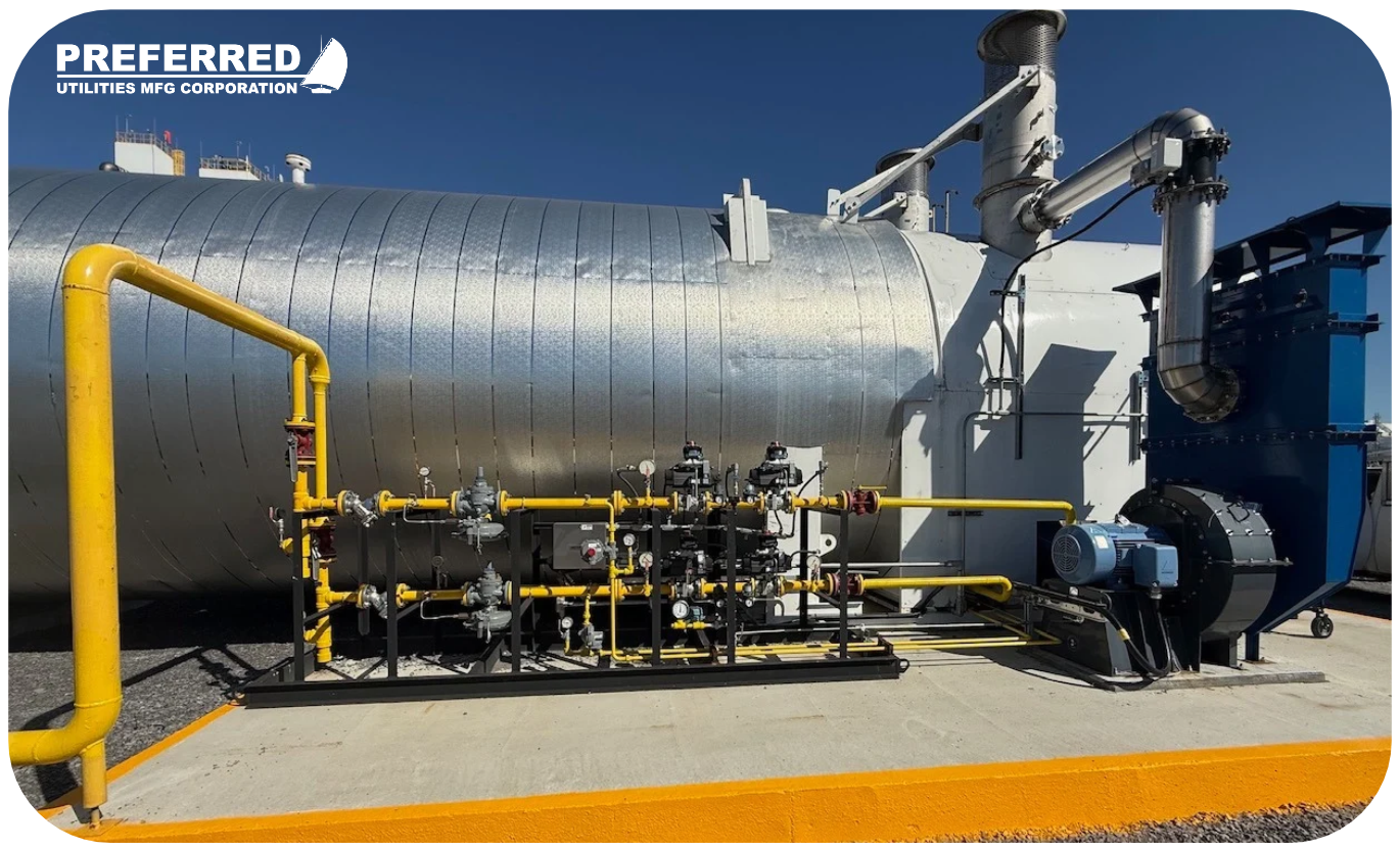
Fuel train piping rack
Natural gas is delivered to the burners through dual fuel trains, one for Burner A and one for Burner B, mounted on a common piping rack. Preferred designed the rack to minimize footprint while keeping valves and components accessible for maintenance and inspection.
Burner management and combustion controls
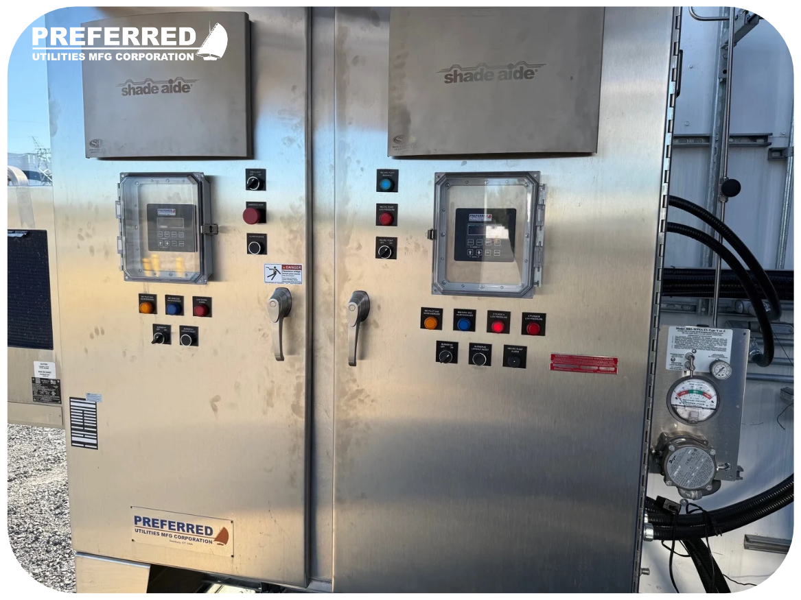
Each burner is controlled by a dedicated burner management system (BMS) and combustion control system (CCS) built on Preferred BMU controllers. The BMS handles the safety functions: purge sequencing, ignition, flame supervision, and safety interlocks. The CCS manages firing rate and fuel-air ratio to match heat demand.
Assigning a separate BMS/CCS to each burner keeps the safety logic and control loops for Burner A and Burner B independent. This simplifies operation and troubleshooting and allows each burner to be started, stopped, or serviced on its own.
Control enclosure and hazardous area classification
The BMS/CCS equipment is housed in a large outdoor-rated control enclosure designed for Class I, Division 2 locations. Class I, Division 2 applies to areas where flammable gases or vapors are not normally present but may be present under abnormal conditions, a typical classification around natural gas equipment in process facilities.
Power distribution panel with Type Z purge
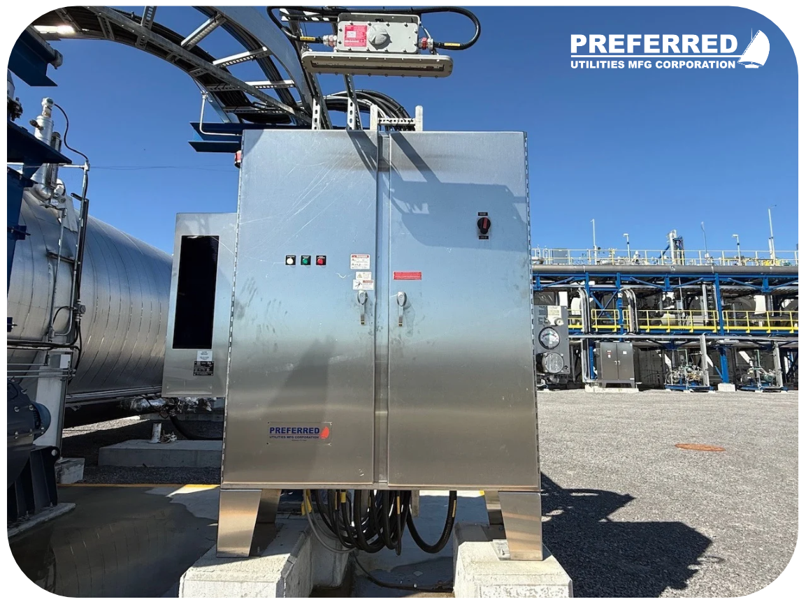
A separate power distribution panel houses the motor VFDs and the power equipment for the recirculation pumps and heater. The panel is equipped with a Type Z purge system. Under NFPA 496, Type Z pressurization reduces the classification inside an enclosure from Division 2 to unclassified by maintaining positive pressure with clean air, allowing general-purpose electrical equipment to be used inside the enclosure.
Climate control
All panels are equipped with air conditioning units to hold internal temperatures within the operating range of the controls and drives. Stable enclosure temperatures protect VFDs and controllers from heat-related derating and premature component failure.
Fuel train piping rack
Natural gas is delivered to the burners through dual fuel trains, one for Burner A and one for Burner B, mounted on a common piping rack. Preferred designed the rack to minimize footprint while keeping valves and components accessible for maintenance and inspection.
Single-source responsibility
Because the burners, controls, power distribution, and fuel trains were engineered together, interfaces between components were defined and verified before shipment. Burner capacities, fuel train sizing, control logic, and panel ratings were coordinated within one design team, giving the customer a single point of accountability from submittal through startup.
For projects involving tight footprints, low NOx requirements, or hazardous area classifications, Preferred knows how to design a seamless application.